PRO-710HD, PRO-610HD, PRO-510HD, SD-582HD5, SD-532HD5
1. SAFETY INFORMATION
1.3 CHARGED SECTION, HIGH VOLTAGE GENERATING POINT AND X-RAY PROTECTION
7 Charged section
The circuit in which the commercial AC power is used as it is without passing through the power supply transformer. If the charged section is touched, there is a risk of electric shock. In addition, the measuring equipment can be damaged if it is connected to the GND of the charged section and the GND of the non-charged section while connecting the set directly to the commercial AC power supply. In this case, be sure to connect the set via an insulated transformer and supply the current.
7 High voltage generating point
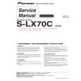
The place where voltage is 100V is generated. 1.Charged seciton DEFLECTION assy (including FBT) (30.5kV, 1.2kV, 210V,135V) 2. POWER SUPPLY assy (135V) 3. R. CRT DRIVE assy (10.5kV, 210V) 4. G. CRT DRIVE assy (10.5kV, 210V) 5. B. CRT DRIVE assy (10.5kV, 210V) 6. CRT assy R (CRT service assy R) (30.5kV) 7. CRT assy G (CRT service assy G) (30.5kV) 8. CRT assy B (CRT service assy B) (30.5kV) 9. Focus variable resistor(VR1) (10.5kV) 10. Deflection yokes (L1, L2 and L3) Approx. (1100V at peak)
7 Charged section (Power supply primary side)
1. The primary side of the AC IN assy 2. AC power cord 3. The primary side of the POWER SUPPLY assy 4. AC power cord for DTV STB (PRO-710HD, PRO-610HD and PRO-510HD Only) : Part is the charged section. : Part is the high voltage generating points other than the charged section.
7 X-ray protection
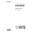
Regarding the parts which are relative to radiation of Xrays (There is the danger to radiate X-ray from the individual CRT assy R, G, B), there are notifications of caution in the individual schematic diagrams. Be sure to read them for safety�s sake. The component parts for X-ray protection are as follows : When the current flows to the CRT assy R, G, B, be sure to perform it with these parts being attached. Protection from the X-ray radiation is maintained in the state in which these parts have been installed to the CRT assy. R, G, B. Accordingly, never supply current only to the CRT assy R, G, B. Moreover, the anode voltage of the CRT assy R, G, B should always be kept not higher than the predetermined value (in the minimum brightness and picture state when non signal input is less than 30.5kV). Be sure to drive the CRT assy R, G, B by using a completely functional DEFLECTION assy which have been adjusted completely in the combined state. (When the voltage abnormally becomes high, the X-ray protection circuit will operate.) 1. CRT assy R, G, B (Do not dismantle CRT assemblies under any circumastances) 2. Each Lens assy
Each Lens Assy
AC power cord for DTV STB
PRO-710HD, PRO-610HD, PRO-510HD High Voltage generating point High Voltage generating point Only
Charged section
High Voltage generating point AC Power cord
Fig. 1 Charged section and high voltage generating point
CRT Assy R, G, B
Fig. 2 Component parts for X-ray protection
3